This computation is quite difficult to conduct exactly and only numeric methods like finite elements will give an accurate result. In almost all practical applicatiosn however, a very high accuracy is not needed and only an order of magnitude is required. That is the case In audio, where the best possible subjective result is wanted making transformer finalization possible only by experimentation. We will deal with an elementary case, yet often encountered, letting the reader adapt it for its particular needs. The studied configuration will be two circular and concentric windings :
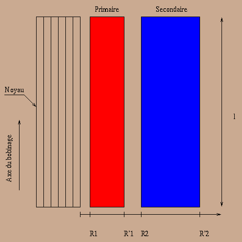
The two windings will have the same length l, start and end radius
respectively ![]() and
and ![]() . Under those
hypothesis, magnetic field in (
. Under those
hypothesis, magnetic field in (![]() ) and between (
) and between (![]() ) the
windings will be given by :
) the
windings will be given by :
with F magnetic power of winding (![]() , with
magnetizing currrent neglected). Firs of all we will compute magnetic
energy contained in each winding :
, with
magnetizing currrent neglected). Firs of all we will compute magnetic
energy contained in each winding :
![]()
then the inductance by the relation :
![]()
It can be admitted that reluctance is dominated by field lines inside
windings. Putting ![]() and
and ![]() mean windings diameters and
mean windings diameters and ![]() mean diameter between windings, an easy computation yields :
mean diameter between windings, an easy computation yields :
Total magnetic energy is thus :
![]()
and from that leakage inductance seen at the primary is :
![]()
If now windings are separated like in the drawing below (``sandwich''
windings), computation can be done by reducing to m elementary transformers :
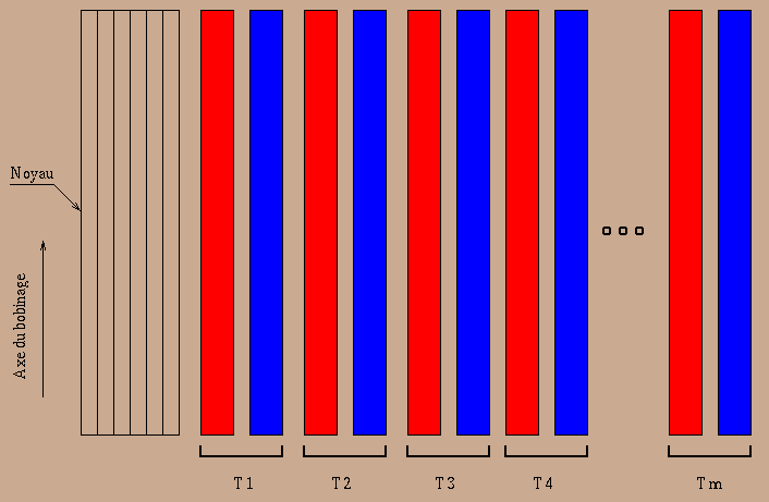
It is easely seen that total inductance seen at primary is lowered by a factor m. This procedure for leakage inductance reduction is the one generally used in audio transformers for expanding band pass to the high frequencies. Practicaly, about 2 to 20 layers can be found (increasing the number of layers makes realization akward). It is still possible to decrease leakage inductance by decreasing number of turns in windings, which is possible with higher permeability cores. It may be necessary for that purpose to use nickel alloy luke permalloy, mumetal or supermalloy. The cost of these materials and their high intrinsic distorsion can more than compensate their interest in leahage inductance reduction. In any case, using special cores is reserved for so-called esoteric amplifiers where cost is a secundary concern. For interstage transformers and (for some output ones too) multifilar windings will boost the primary-secundary coupling. Some well designed realization have reached 300 kHz band-pass. It worth mention too coaxial windings, in which screen plays the role of secundary while internal wires are parts of the primary (if you have a ratio transform less than unity of course) : with even higher performance, the Mhz band-pass can be reached ... for a stratospheric price!
Note
When designing push-pull output transformer, care must be taken of the leakage inductance between the two half-primaries (it can be obviously computed the same way as primary-secundary leakage). In pure A class, nothing bad will happen, but in B class, only half of wave will flow in each half-primary. The inter primary leakage inductance will then produce an extra current when tubes will switch on and off, what generates a very special kind of distrosion : switching ''clicks'' :
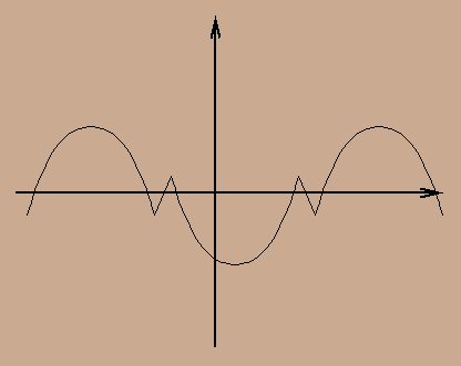
This phenomenon is extremely annoying and give a harsh sound. It's of primary importance to take a special care of half-primaries coupling when designing a class B output stage.