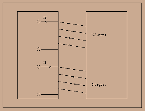
Schematicaly, a transformer is composed of two windings with some of their flux in common :

In the case we are interested in, a high permeability core is used as
common support of those windings and concentrate magnetic
flux. Faraday's law allows voltages at the first and second windings
to be written as a function of the flux ![]() and
and ![]() thru them :
thru them :

In previous formulas, ![]() and
and ![]() stand for the respective
resistances of the windings 1 and 2. In applications, the input
winding is called the primary of the transformer, while the ouput one
is called the secondary (this naming is application dependent: a
single phase transformer can be loaded from any of its windings). We
will admit in the following the primary has index 1 and secundary
index 2. In the previous system of equations it is possible to
decompose flux
stand for the respective
resistances of the windings 1 and 2. In applications, the input
winding is called the primary of the transformer, while the ouput one
is called the secondary (this naming is application dependent: a
single phase transformer can be loaded from any of its windings). We
will admit in the following the primary has index 1 and secundary
index 2. In the previous system of equations it is possible to
decompose flux ![]() and
and ![]() in common and proper part. This
yields to the following notation :
in common and proper part. This
yields to the following notation :
![]()
with ![]() and
and ![]() respective numbers of turns of the windings,
respective numbers of turns of the windings,
![]() commun flux and
commun flux and ![]() proper flux (called
leakage flux). The system of equations becomes :
proper flux (called
leakage flux). The system of equations becomes :

Leakage flux ![]() is generated only by primary current
is generated only by primary current ![]() ,
and we can associate to it a self-inductance
,
and we can associate to it a self-inductance ![]() such that
such that
![]() (strictly speaking, since an iron core is
ferromagnetic, this is not true, but the high permeability of the core
implies that the reluctance of the induction tubes giving
(strictly speaking, since an iron core is
ferromagnetic, this is not true, but the high permeability of the core
implies that the reluctance of the induction tubes giving ![]() is dominated by the reluctance of the air part of it). Likewise, we
will put
is dominated by the reluctance of the air part of it). Likewise, we
will put ![]() . Inductances
. Inductances ![]() and
and ![]() are
called primary and secundary leakage inductances. When the secundary
circuit is open, a current
are
called primary and secundary leakage inductances. When the secundary
circuit is open, a current ![]() flows thru the primary : it is called
the magnetizing current. Bu putting
flows thru the primary : it is called
the magnetizing current. Bu putting ![]() , we have :
, we have :

or equivalently with ![]() :
:

In other words, a real transformer can be modelled as a perfect
transformer (with leakage or resistance) with parasitic elements
(resistances and inductances) connected to it. For a perfect
transformer, one has the relation ![]() , the
quantity
, the
quantity ![]() beeing the transformation ratio. In
a loaded iron core transformer, the magnetizing curre
beeing the transformation ratio. In
a loaded iron core transformer, the magnetizing curre ![]() will be
negligible with respect to other currents and we will have
will be
negligible with respect to other currents and we will have ![]() . Those two relations show that a perfect transformer loaded
on the primary by an impedance Z will show an impedance
. Those two relations show that a perfect transformer loaded
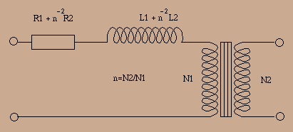
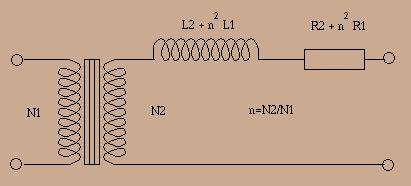
on the primary by an impedance Z will show an impedance ![]() at the secundary. With this, we can make three equivalent schemas of a real transformer :
at the secundary. With this, we can make three equivalent schemas of a real transformer :


Note that since leakage inductances are in series, they will tend to limit response at high frequencies while the finite permeability of the core will limit it at low frequencies.