General electromagnetic phenomenons can be describe with the four Maxwell's equations :

The quantities appearing beeing those :
Vectors E and D are linked by the polarisability of the material :
in vacuum, one have simply ![]() with
with ![]() is the permittivity of vacuum, in Farads per
meter. In polarisable matter, relationship between E and D is
generally non linear, namely D = f(E). In most cases, f will admit
a serie expansion in a neighborood of 0, yielding :
is the permittivity of vacuum, in Farads per
meter. In polarisable matter, relationship between E and D is
generally non linear, namely D = f(E). In most cases, f will admit
a serie expansion in a neighborood of 0, yielding :
![]()
Except when dealing with extremely high fields or with ferroelectric
substrates (like KDP, baryum titanate, Seignette salt), there is no
need to use non-linear terms in the previous expansion. The
relarionship is then purely linear
![]() with
with ![]() an order 2 tensor called permittivity
tensor (one often writes
an order 2 tensor called permittivity
tensor (one often writes ![]() , with
, with
![]() called relative permittivity tensor). When fields are
time varying, the phase variations can be modelled by taking a complex
called relative permittivity tensor). When fields are
time varying, the phase variations can be modelled by taking a complex
![]() .
In an isotropic material, is a scalar value, which is
called permittivty (in the time-varying context, the ration between is
imaginary and real part is the loss angle tangent, a quantity often
given by dielectric and capacitors makers : the lower this angle is,
the lower losses will be in high-frequency). Be careful that altough
in most practical cases the isotropic formulation is valid, some
dielectric are purposely made anisotropic, mainly in high-voltage
applications ... or in some audio cables.
.
In an isotropic material, is a scalar value, which is
called permittivty (in the time-varying context, the ration between is
imaginary and real part is the loss angle tangent, a quantity often
given by dielectric and capacitors makers : the lower this angle is,
the lower losses will be in high-frequency). Be careful that altough
in most practical cases the isotropic formulation is valid, some
dielectric are purposely made anisotropic, mainly in high-voltage
applications ... or in some audio cables.
Vector H and B are likewise functionnaly dependent B = f(H), but
now most materials used in transformer building are anisotropic and
non linear (except air of course!). In the case where first order
expansion is valid, one put
![]() , (in vacuum,
, (in vacuum, ![]() , with
, with
![]() and relative permeability
and relative permeability ![]() is defined
by
is defined
by ![]() ).
). ![]() is expressed in Henries per meter
(
is expressed in Henries per meter
(![]() ). In other cases it will be necessary to use the complete
function B = f(H). Furthermore, relationship B = f(H) is in fact
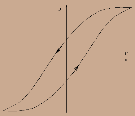
described by a cycle, called hysteresis cycle, since induction is dependent on
previous values of H! The figure below shows an hysteresis cycle,
with its orientation.
). In other cases it will be necessary to use the complete
function B = f(H). Furthermore, relationship B = f(H) is in fact
described by a cycle, called hysteresis cycle, since induction is dependent on
previous values of H! The figure below shows an hysteresis cycle,
with its orientation.

One can note the flattening of the curve for high absolute values of H : the phenomenon is known as the material saturation.
Maxwell's equations admit an integral form, that can be obtained by applying Stokes or Ostrogradsky's formula. This formulation yields to well known laws :

In previous formula, S (resp. V) stand for a surface
(resp. volume) of ![]() , with a regular boundary
, with a regular boundary ![]() (resp.
(resp. ![]() ). In the following, an expression like
). In the following, an expression like ![]() will be denoted by
will be denoted by ![]() (it's the flux of magnetic induction
thru the surface S).
(it's the flux of magnetic induction
thru the surface S).
Depending on applications, it can be easier to use integral forms
instead of differential ones : that will be the case for a winding on
an iron core (or on any high permeability material). It worth noting
that the relation ![]() , field lines of B are
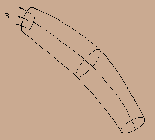
closed, and it is useful to take into account the regions of space
bounded by all field lines originated from a given curve :
, field lines of B are
closed, and it is useful to take into account the regions of space
bounded by all field lines originated from a given curve :

Those regions are called induction tubes and have the noticeable
property that the flux ![]() of B is constant on each of its normal
sections.
We then deduce that, using Ampere's law, the flux
of B is constant on each of its normal
sections.
We then deduce that, using Ampere's law, the flux ![]() can be
written as :
can be
written as :

where the integral is computed along a field line belonging to the
induction tube, ![]() beeing the material permeability at the
computation point and S the normal section at that point. The sum of
currents
beeing the material permeability at the
computation point and S the normal section at that point. The sum of
currents ![]() flowing thru the induction tube is expressed in
Amperes-turn in the case of a winding. The integral appearing in
denominator is the total reluctance of the tube. It is possible to
define the reluctance of a part of a tube simply by restricting
integration to that part. It is then clear that, by additivity of
integrals, reluctances follow formaly the same laws than resistances
(one can combine reluctances in series or in parallel depending on the
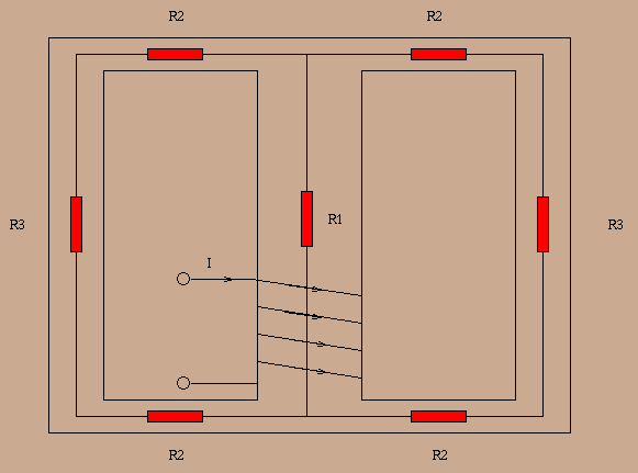
way an induction tube is cut into several branches). The drawing below
shows how an iron core can be cut into branches of known reluctances
(each rectangle stands for the reluctance of a part of the core
with constant section and permeability). The total reluctance of the
core can then be computed using the composition law previously give
(note the perfect analogy with the case of resistances!). Since
ferromagnetic materials
have generally a very high permeability, the whole core can be thought
as an induction tube.
flowing thru the induction tube is expressed in
Amperes-turn in the case of a winding. The integral appearing in
denominator is the total reluctance of the tube. It is possible to
define the reluctance of a part of a tube simply by restricting
integration to that part. It is then clear that, by additivity of
integrals, reluctances follow formaly the same laws than resistances
(one can combine reluctances in series or in parallel depending on the
way an induction tube is cut into several branches). The drawing below
shows how an iron core can be cut into branches of known reluctances
(each rectangle stands for the reluctance of a part of the core
with constant section and permeability). The total reluctance of the
core can then be computed using the composition law previously give
(note the perfect analogy with the case of resistances!). Since
ferromagnetic materials
have generally a very high permeability, the whole core can be thought
as an induction tube.

With that approximation, we will admit too that upper and lower
branches and right and left branches respectively have the same
reluctance. The total reluctance is then :
![]()
If the winding has N turns and if the central section of the core is
S, one can deduced the induction from the previous formula :
![]()
THis quantity is very important for the design of a transformer : the
relationship between B and H beeing non linear, it will exist a
maximum admissible value for the induction (that is a distorsion limit
for audio applications). This limiting value appears most of the time
in the data sheets of the core maker, but can be deduced from the
curve B = f(H) too ... or by experience! A classical value of
![]() for silicon-iron cores will be between 0.2 and 0.4 Teslas,
but can be lowered for minimum distorsion or when using very high
permeability materials (nickel alloys like permalloy, mumetal,
supermalloy). If the permeability
for silicon-iron cores will be between 0.2 and 0.4 Teslas,
but can be lowered for minimum distorsion or when using very high
permeability materials (nickel alloys like permalloy, mumetal,
supermalloy). If the permeability ![]() is constant (which is valid
for any commercial cores, except those with an air gap), the formula
giving B will become :
is constant (which is valid
for any commercial cores, except those with an air gap), the formula
giving B will become :
![]()
where ![]() is a length called mean lenght of field lines : it can be
found in data sheets of the core.
is a length called mean lenght of field lines : it can be
found in data sheets of the core.